


This article was written by Heinz P Bloch, mechanical engineering authority, consultant and author. Mr. Bloch has written 18 books and over 480 technical papers on practical machine management, reliability engineering, oil mist lubrication and similar topics.
It has long been recognized that as many as 91%[1] of all the rolling element bearings installed in the world’s machinery fall short of reaching the manufacturer’s calculated L-10 life[2].
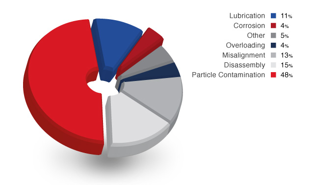
Causes of Bearing Failure
Lubricant contamination

Research and follow-up analysis by bearing producers and users has established lubricant contamination as the predominant failure cause [3] (see chart above). Much of this contamination finds its way into bearing housings through openings where equipment shafts protrude through bearing housings, or at vents and breathers provided somewhere on the oil-lubricated assembly. Also, bearing housings undergo temperature shifts from daytime to nighttime, and temperatures differ when operating versus non-operating. With increasing temperatures, the vapors floating above the liquid oil level will expand; with decreasing temperatures the vapors will contract. In a closed volume, increasing temperatures cause pressures to go up, while decreasing temperatures cause pressures to decrease. The laws of physics are at work here.The image on the right Illustrates the consequences of this contamination.
The trouble with lip seals
 Historically the most common way of protecting bearings was
to use a lip seal (see inset). They rely on surface contact between the seal lip and the shaft to form the seal. This surface contact often results in costly damage to the shaft itself (left). In addition, as a consequence of this
rubbing, lip seals can’t fully protect the bearing from moisture or particle ingress, which ultimately results in bearing failure. Today however it is generally accepted that lip seals have limitations[4], but due to inexpensive initial cost they continue to be widely applied. Lip seals do not meet the requirement of IEEE standard 841-2001[5] for electric motors or American Petroleum
Institute standard API610 11th Edition[6] (section 6.10.2.6)
Historically the most common way of protecting bearings was
to use a lip seal (see inset). They rely on surface contact between the seal lip and the shaft to form the seal. This surface contact often results in costly damage to the shaft itself (left). In addition, as a consequence of this
rubbing, lip seals can’t fully protect the bearing from moisture or particle ingress, which ultimately results in bearing failure. Today however it is generally accepted that lip seals have limitations[4], but due to inexpensive initial cost they continue to be widely applied. Lip seals do not meet the requirement of IEEE standard 841-2001[5] for electric motors or American Petroleum
Institute standard API610 11th Edition[6] (section 6.10.2.6)
Benefits of Bearing Isolators
As a consequence of these findings and in an effort to reduce the pressure-related alternating in-and-out flow of contaminated ambient air, conventional labyrinths are often replaced by rotating labyrinth seals, which are often called bearing isolators or bearing protectors, for short. It should be noted that these rotating devices are designed with inherent clearances. In essence, an air gap separates the rotating and stationary elements. Except for brief time periods when the gap may be bridged by an oil film, this air gap is large enough to allow the continual exchange or inflow-outflow of atmospheric air with its ever-present contaminants, primarily water vapor and air-borne dust.
It has been pointed out that bearing isolators work best when the housing vent is plugged. It has also been noted that, if the housing vent is left open, the slight vacuum created by certain “contaminant expulsion elements”---often just a contour milled into one of the machined components---will induce the flow of airborne dust, dirt, vapors and everything available in the immediate environment through the bearing enclosure. With large clearances the action is not unlike an oil bath style vacuum cleaner. This action is constant and the amount of induced debris build-up can be significant.
Dynamic O-rings
 Bearing isolators fitted with dynamic O-rings (right) try to close
the gap through which airborne contaminants can enter into the bearing housing. The design intent is for the O-ring to effectively seal off the air gap at standstill (Ref. 2). As the shaft starts rotating, the designers or manufacturers anticipate
that centrifugal force acting on the rotating O-ring will cause this O-ring to lift off. In other words, the design objective is for the lifting distance to be sufficient to avoid the scraping and galling wear modes noted on circumferentially
contacting dynamic O-rings.
Bearing isolators fitted with dynamic O-rings (right) try to close
the gap through which airborne contaminants can enter into the bearing housing. The design intent is for the O-ring to effectively seal off the air gap at standstill (Ref. 2). As the shaft starts rotating, the designers or manufacturers anticipate
that centrifugal force acting on the rotating O-ring will cause this O-ring to lift off. In other words, the design objective is for the lifting distance to be sufficient to avoid the scraping and galling wear modes noted on circumferentially
contacting dynamic O-rings.
Common sense tells us that devices with circumferentially contacting dynamic (“flying”) O-rings (see right) cannot seal tightly if the O-ring (made from a polymer material) scrapes on the sharp corners of an oil ring retention groove. But neither can the devices seal tightly if the retention groove is chamfered; in that case the resulting air gap is too large. Long-term effective sealing is simply not possible with circumferential dynamic O-rings.
O-rings in dynamic applications
It is for these rather obvious reasons that O-ring manufacturers do not recommend high-cycle dynamic circumferential sealing applications. Nevertheless, bearing protectors/isolators equipped with dynamic “vapor blocking” O-rings are likely to outperform simpler models of bearing housing protectors (bearing isolators) that do not have blocking rings.
As regards bearing isolators that incorporate dynamic O-rings of any kind, many practicing engineers have voiced concerns over mistaken claims that these devices provide hermetic sealing. Reliability professionals are correctly reasoning that if an O-ring does lift off, there will still be the gap through which contaminated air moves either into the bearing housing or out of the bearing housing---depending on prevailing temperatures and pressures. Conversely, if there is no gap, there will be wear. It can thus be shown that, contrary to written claims dating back about two decades, no bearing protectors/isolators designed with dynamic O-rings will be capable of “hermetic” sealing duty.
However, third-generation bearing isolators - as used in the LabTecta® - developed in 2003 are able to fully circumvent issues with radially outward-moving dynamic O-rings. Instead, they use an axially outward-moving O-ring which can only make contact with a large, contoured sealing area (large area equals low contact pressure). At standstill, this large diameter O-ring is being activated by a narrower profile outward-moving dynamic O-ring. At operation, the dynamic O-ring exerts little, if any, load on the larger axially sliding O-ring. While not “absolutely hermetic”, the LabTecta®-style design exhibits no discernible wear after years of operation.
Magnetic Seals for Hermetic sealing
Hermetically sealing the bearing housing implies that nothing enters and nothing escapes. Only face-to-face sealing devices - mechanical seals - meet this definition most closely. However, in view of the generally limited axial space available between bearing housings and fluid casings of centrifugal pumps and other machinery, relatively narrow-width, magnetically closing face seals have been developed in the recent decades.
 Whenever there exists a thin film of clean oil between either
spring-activated or magnet-activated seal faces, long seal life and hermetic containment of the lubricating fluids results. Tens of thousands of the magnetic face seals shown on the left have been used in aircraft task pumps, as aircraft
generator seals, and on vertical stabilizer units[7]. They can tolerate rubbing velocities as high as 86 m/s (17,000 fpm) and temperatures as high as
200o C (392o F) and have frequently served to everyone’s satisfaction for over 50,000 operating hours. These seals have performed equally well in such industrial applications as gun drills, gearboxes and pump housings.
They use a single Al-Ni-Co magnet annulus to attract the opposing seal face.
Whenever there exists a thin film of clean oil between either
spring-activated or magnet-activated seal faces, long seal life and hermetic containment of the lubricating fluids results. Tens of thousands of the magnetic face seals shown on the left have been used in aircraft task pumps, as aircraft
generator seals, and on vertical stabilizer units[7]. They can tolerate rubbing velocities as high as 86 m/s (17,000 fpm) and temperatures as high as
200o C (392o F) and have frequently served to everyone’s satisfaction for over 50,000 operating hours. These seals have performed equally well in such industrial applications as gun drills, gearboxes and pump housings.
They use a single Al-Ni-Co magnet annulus to attract the opposing seal face.
A rather similar seal, incorporating a series of strong rare-earth magnet rods that attract the opposing face. Superior face material combinations achieve coefficients of friction that, even without lubrication present, rival those of PTFE.. Many thousands of fluid machines in different parts of the industrial world have been fitted with these particular types of magnetic seal.
It should be pointed out that magnetic seals obtain lubrication and cooling from the ever-present oil fog that surrounds oil-lubricated bearings. Properly designed, using appropriate face materials and applying suitable selection criteria, they represent the ideal choice of a bearing housing seal that prevents both egress of lube oil and ingress of atmospheric contaminants. Should the temperature-dependent pressure inside a non-vented bearing housing rise and overcome the magnetic closing force, the magnetic face seal would instantly release this pressure by opening and immediately re-closing.
 Magnetic seals of the type shown on the left will
perform flawlessly, either in conjunction with pressure-balanced constant level lubricators or non-vented bearing housings filled with a finite amount of liquid lubricant. An even more advanced dual magnetic face seal variant, (“MagTecta®”, shown right), has been available since 2005. It represents the ideal bearing housing closure for closed, environmentally acceptable oil mist
lubrication systems.
Magnetic seals of the type shown on the left will
perform flawlessly, either in conjunction with pressure-balanced constant level lubricators or non-vented bearing housings filled with a finite amount of liquid lubricant. An even more advanced dual magnetic face seal variant, (“MagTecta®”, shown right), has been available since 2005. It represents the ideal bearing housing closure for closed, environmentally acceptable oil mist
lubrication systems.
In a closed oil mist application, the oil mist is introduced in the space between magnetic seal and bearing[8] . Excess liquid or vaporized oil is led off or collected at the bottom center location of the bearing housing[9].
[1] The Barden Bearing Company, Commercial Sales Bulletin, 1990
[2] L-10 life is the number of operating hours where 10% of an identical bearing population will either have failed, or will exhibit visible or measurable damage
[3] Ref IDCON, Maintenace Technology, SKF, RP, Pioneer Motor Bearing, Zeiden cited by Bloch, Heinz: The Pump Users Handbook: Life Extension 2011
[4] Heinz Bloch, “Rotating Seals or lip seals” Plant Engineering July/August 2014
[6] http://www.americanpetroleuminstitute.com/
[7] Cited by Heinz Bloch “Bearing protection and equipment reliability: Part II – What is really justified?” Pumps & Systems October 2001. http://www.sealing.com/fileadmin/docs/ISOMAG_Pump_Zone_Reprint.pdf
[8] Heinz Bloch, Abdus Shamim; “ Oil Mist Lubrication: Practical Applications” The Fairmont Press, Lilburn GA, 2000
[9] Heinz Bloch; “Practical Lubrication for Industrial Facilities”, The Fairmont Press, Lilburn GA, 2001. P28-35
